How Do Gear Pumps Work?
Gear pumps are one of the most common types of positive displacement pumps, used across industries to move fluids with precision. They are particularly valued for their reliable flow rate and consistent pressure. This article will explore how gear pumps work, the types available, and their key applications in the automation industry.
Understanding Gear Pumps: The Basics
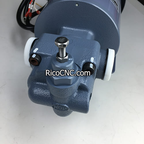
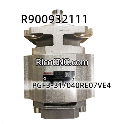
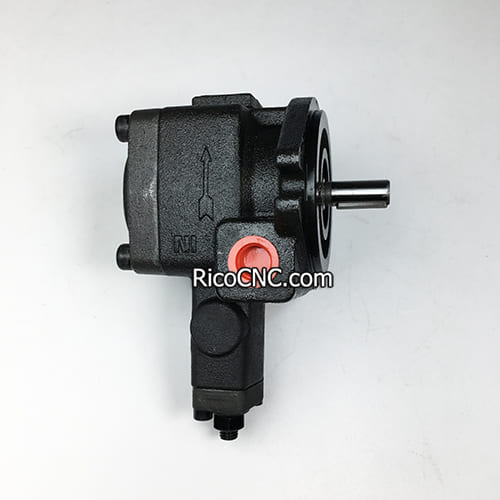
A gear pump works by using the motion of gears to create suction, drawing fluid from an inlet and expelling it through an outlet. This positive displacement mechanism ensures a steady and controlled movement of fluid, making it ideal for a range of applications, from automotive engines to industrial fluid systems.
The core components of a gear pump include:
Drive Gear: Powered by an external source, which initiates the motion.
- Idler Gear: Engaged by the drive gear, contributing to the movement of fluid.
- Casing: Houses the gears and helps direct fluid through the system.
The operation of a gear pump is simple: the gears mesh together, trapping fluid in cavities between the teeth and the casing. As the gears rotate, the trapped fluid is moved towards the outlet port, generating consistent pressure and flow.
For those interested in components for gear pump systems, you may refer to the Parker PEC5-220V-D Single Solenoid Valve used in similar fluid flow applications. See more details here.
Types of Gear Pumps
Gear pumps can be categorized primarily into two types: internal gear pumps and external gear pumps. Each type has unique features, making them suitable for various fluid-handling applications.
Internal Gear Pumps
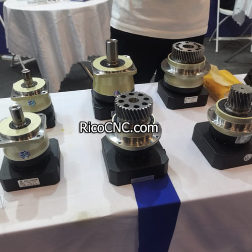
Internal gear pumps have a rotor gear that meshes with a smaller, inside gear known as the idler gear. The idler gear sits within the larger gear and helps to move fluid in a continuous flow. The space between the gears forms a cavity, which creates suction as the gears rotate, drawing fluid into the pump.
How Internal Gear Pumps Work: Fluid enters the space between the rotor and the idler. As these gears rotate, the volume of space between them changes, creating suction and pushing the fluid towards the outlet.
Key Applications: They are often used in high-viscosity fluid applications such as pumping oils, paints, and resins. Internal gear pumps are preferred for their smooth flow and quiet operation.
Internal gear pumps are also ideal for handling corrosive materials since their design can better handle highly viscous substances without substantial wear and tear.
For more on suitable industrial flow components, check out the Directional Solenoid Valve from the AVENTICS Series here.
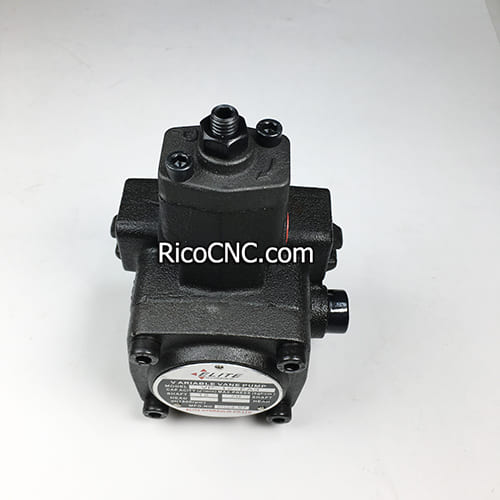
External Gear Pumps
External gear pumps use two identical gears that mesh with each other. These gears rotate in opposite directions, creating a series of sealed cavities to move the fluid. Unlike internal gear pumps, external gear pumps provide higher pressure capability, which makes them suitable for applications needing robust and consistent flow.
How External Gear Pumps Work: As the gears rotate, fluid is trapped between the teeth of each gear and the casing. The motion of the gears pushes this fluid towards the outlet, generating the flow and pressure required.
- Key Applications: These pumps are commonly used for hydraulic fluid power, fuel injection systems, and other applications where consistent pressure is required.
External gear pumps are simple in design, which makes them cost-effective and easy to maintain. They are used extensively in chemical processing and water treatment plants.
To see more components applicable to fluid flow control, you can check out the AVENTICS 5 Way 2 Position Pneumatic Valve here.
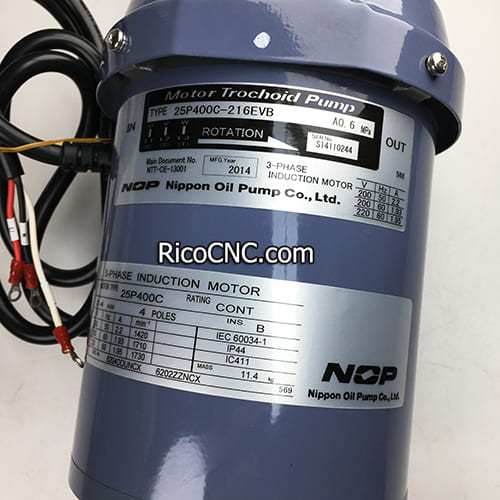
Flow and Pressure in Gear Pumps
The key feature that defines a gear pump is its ability to generate positive displacement, which means a fixed volume of fluid is moved with each gear rotation. This property ensures that gear pumps can maintain steady flow rates despite changes in system pressure, making them ideal for precision tasks.
Mechanism of Flow and Pressure Generation
Inlet Side: As the gears unmesh on the inlet side, they create a void that allows fluid to be sucked into the pump.
- Transfer Process: The fluid is then trapped between the teeth of the gears and the casing, moving along as the gears rotate.
- Outlet Side: When the gears re-mesh on the outlet side, the trapped fluid is pushed out, creating pressure in the outlet stream.
This positive displacement means that gear pumps provide a consistent output regardless of the pressure head. The pump’s flow rate depends primarily on the gear size, rotation speed, and cavity size.
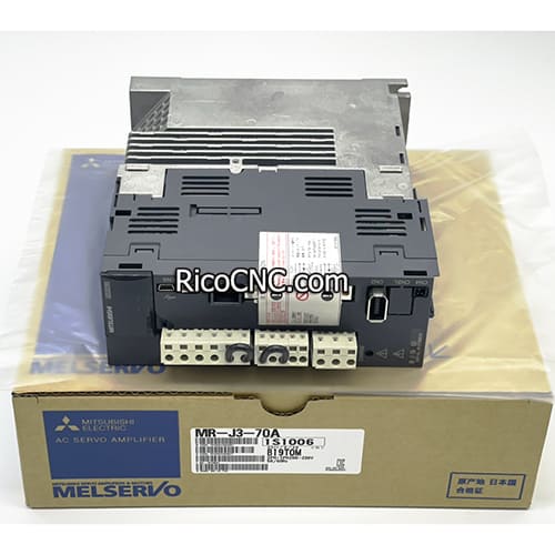
For information on servo systems that support similar automation needs, you can explore Mitsubishi Servo Amplifier Solutions here.
Gear Pump Design Features
The design of a gear pump plays a significant role in its performance. Key features include gear types, material construction, and sealing mechanisms, all of which can be tailored to specific needs.
Material Selection: Gear pumps are often made from materials that resist wear, including stainless steel, bronze, or cast iron. The material selection is particularly important for handling corrosive fluids.
- Seal Types: Mechanical seals or gasket seals are used to prevent leakage. Proper sealing ensures that the pump maintains pressure and prevents air entry, which could cause cavitation.
- Clearance and Efficiency: The clearance between gears and the casing must be tight to prevent slip (fluid leaking back). However, clearances also need to be sufficient to prevent excessive wear.
One important aspect of gear pump design is the idler gear for internal models, which improves efficiency in handling thick, viscous fluids without significant energy loss.
Applications of Gear Pumps
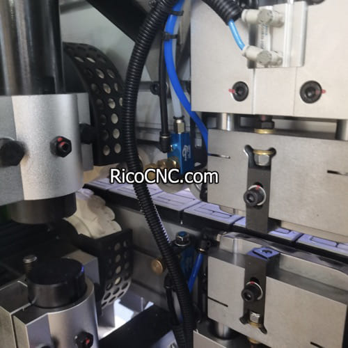
Gear pumps are employed in a diverse range of industries due to their versatility and reliability.
Hydraulic Systems
Gear pumps are commonly used in hydraulic systems to convert mechanical power into hydraulic energy. They provide high-pressure and steady flow, which is crucial for precise control in hydraulic machinery such as forklifts, excavators, and other industrial equipment.
Chemical Processing
In chemical processing, gear pumps are used for metering and transferring chemicals. Their positive displacement mechanism makes them suitable for precise dosage and chemical injection systems where accuracy is key.
Oil and Gas
Oil transfer and lubrication systems in engines often rely on gear pumps due to their ability to handle high-viscosity fluids like oils. Gear pumps are the backbone of lubrication systems, providing constant flow to ensure machinery remains in optimal working condition.
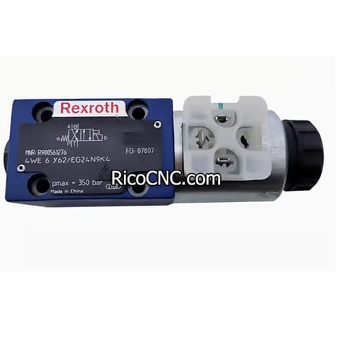
To see more about components ideal for precision flow control, visit our section on Bosch Rexroth Directional Spool Valve Solenoid Valve here.
Common Issues with Gear Pumps and Solutions
Like all mechanical systems, gear pumps may face certain challenges during their operation. Here are some common issues and tips on how to handle them:
1. Cavitation
Cavitation occurs when there is insufficient inlet pressure, leading to vapor bubbles forming and collapsing in the pump. This can cause damage over time.
Solution: Make sure the inlet line is free from obstructions and the pressure is adequate to keep the fluid flowing smoothly.
2. Leakage
Seal or gasket wear can lead to leakage, which reduces the pump's efficiency and may cause fluid contamination.
Solution: Regular inspection and replacement of seals and gaskets can prevent leakage and ensure consistent performance.
3. Overheating
Overheating might occur if the pump is overworked or if fluid viscosity is too high.
Solution: Ensure the pump is used within its operational limits regarding fluid viscosity and pressure. Proper cooling mechanisms should also be in place.
Frequently Asked Questions
1. What are the main types of gear pumps?
There are two main types: internal gear pumps and external gear pumps. Internal gear pumps are ideal for handling thick, viscous fluids, whereas external gear pumps are suited for high-pressure applications with less viscous fluids.
2. Can gear pumps handle high-viscosity fluids?
Yes, gear pumps, particularly internal gear pumps, are designed to handle high-viscosity fluids such as oils, paints, and molasses.
3. What causes cavitation in gear pumps?
Cavitation occurs when the inlet pressure is insufficient, causing vapor bubbles to form within the pump. This can lead to reduced efficiency and mechanical damage.
4. Are gear pumps suitable for chemical processing?
Absolutely. Gear pumps are used in chemical processing for accurate metering and chemical injection, providing consistent flow rates that are essential for these applications.
5. What is the difference between internal and external gear pumps?
Internal gear pumps have a rotor and idler gear, offering quieter and more efficient operation for viscous fluids, whereas external gear pumps use two identical gears and are better for high-pressure tasks.
Conclusion
Gear pumps are highly efficient, versatile, and reliable devices used in a variety of industries. Whether for high-pressure hydraulic systems, chemical metering, or oil transfer, they offer unmatched consistency in fluid movement. Understanding the differences between internal and external gear pumps, and knowing how they generate flow and pressure, can help you make an informed decision for your next project. If you need further guidance on choosing the right pump or other related equipment, feel free to contact us. We are here to provide solutions tailored to your automation and fluid control needs.
