How to Connect a Limit Switch
Connecting a limit switch is a fundamental task in automation, manufacturing, and home automation systems. Limit switches are essential components that help ensure machines operate safely and effectively by controlling movement and signaling the machine’s control system. Understanding how to connect a limit switch is crucial for maintaining system reliability and ensuring operational efficiency. This article will provide a step-by-step guide to connecting a limit switch, along with an in-depth understanding of its types, applications, and practical tips for ensuring a successful connection.
What Is a Limit Switch?
A limit switch is an electromechanical device that detects the presence or absence of an object and initiates a specific action based on that detection. Limit switches can be used to stop a motor, activate an alarm, or provide position feedback. They are commonly used in industrial automation systems, robotics, and mechanical systems like CNC machines and elevators.
The key components of a limit switch are:
Actuator: The physical part that interacts with the moving object.
Contacts: The internal electrical components that open or close depending on the actuator’s position.
Housing: Provides protection for the internal components and ensures durability in harsh environments.
These components work together to detect motion or position and respond accordingly by altering the electrical circuit in the system. Understanding the basics of these switches helps in efficiently setting them up for practical use.
For more advanced systems, consider our PHS520S-8 Parker PEC5-220V-D Single Solenoid Valve for precise control in automation systems. 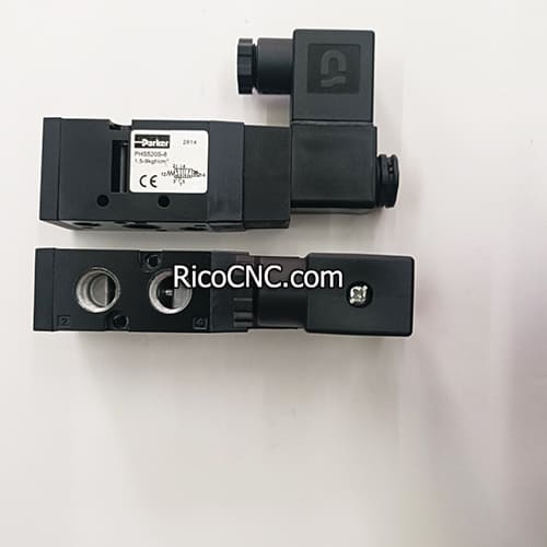
Types of Limit Switches and Their Applications
Before connecting a limit switch, it is essential to understand the various types available. Limit switches come in different forms, each suited for specific applications. Here are some of the most common types:
1. Lever-Type Limit Switch
This switch has a lever arm with a roller at its end, making it ideal for use in conveyor systems where items move along a track. The lever actuates the switch when an object makes contact with it.
2. Plunger-Type Limit Switch
This switch has a spring-loaded plunger that activates the internal contacts. It is used in applications where direct linear movement can be used to press the plunger, such as in elevator door mechanisms.
3. Rotary Limit Switch
This type uses a rotary motion to activate the contacts. It is often used in applications requiring a rotating cam to engage or disengage the switch.
4. Magnetic Limit Switch
Magnetic limit switches are used where non-contact detection is necessary. They work well in dusty environments or areas where physical contact may damage the components.
For advanced solutions in industrial environments, consider the Bosch Rexroth Directional Spool Valve, which works well with automation systems requiring precise component placement.
Tools and Materials Needed to Connect a Limit Switch
Before beginning the connection, gather the following tools and materials:
Limit Switch: Ensure you have the appropriate type of limit switch for your specific application.
Screwdriver: Used for attaching the switch to the mounting surface.
Multimeter: For testing continuity.
Wires: Use appropriately rated wires for the system's voltage and current levels.
Wire Strippers: For stripping insulation from the wires.
Electrical Tape: To secure connections and provide insulation.
For precise diagnostics and sensor integration, the Wenglor Reflex Sensor can be considered for applications that require high accuracy. 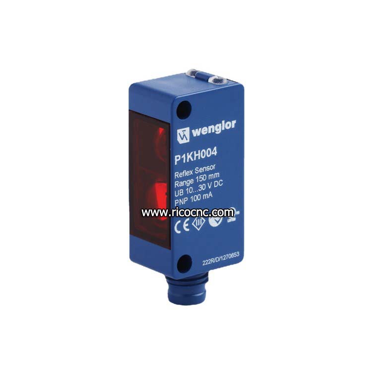
Step-by-Step Guide on Connecting a Limit Switch
Step 1: Turn Off Power
Before working on the system, turn off all power to prevent accidental electric shock. Safety is crucial, as working with live electrical components can be dangerous.
Step 2: Mount the Limit Switch
Mount the limit switch at the desired location on the machine or control system. This position should be where the actuator will interact with the moving part of the equipment. Ensure it is securely fixed to prevent it from shifting during operation.
Step 3: Connect the Wires
Strip the Wires: Use a wire stripper to strip about 1/4 inch of insulation from each wire that will be connected to the limit switch.
Attach the Wires to Terminals: Limit switches generally have Normally Open (NO) and Normally Closed (NC) terminals. Depending on your circuit requirement, connect the wires to the appropriate terminals.
Connect the power wire to the common terminal.
If the switch is intended to stop the system when activated, connect the output wire to the NC terminal.
If the switch should start a function when activated, connect to the NO terminal.
Secure the Wires: Tighten the terminal screws to secure the wires in place.
Step 4: Test for Continuity
Using a multimeter, test the continuity of the circuit. Set the multimeter to measure ohms, and place the probes on the terminals. The switch should show continuity when the actuator is pressed if connected to the NC terminal.
For additional features like advanced system diagnostics, consider integrating Aventics Pneumatic Solenoid Valve Series 840, which can be used in tandem with limit switches to control pneumatic systems efficiently.
Step 5: Secure All Connections
After confirming that the circuit functions correctly, secure all electrical connections with electrical tape or appropriate fittings to prevent exposure or short circuits. This ensures safety and reliability during the operation of your machinery.
Step 6: Power On and Test the System
After all connections are made and secured, turn the power back on. Test the operation of the limit switch by moving the machine part that comes in contact with the actuator. Observe if the machine responds as expected—such as halting or triggering an action.
Common Mistakes When Connecting Limit Switches and How to Avoid Them
1. Incorrect Terminal Connection
Using the wrong terminal (e.g., connecting to NO when NC is required) is a common mistake that can lead to unintended machine operations. Always check the wiring diagram before making connections.
2. Loose Connections
Loose connections can cause arcing, overheating, or intermittent failures. Ensure all terminal screws are tightened securely to avoid these issues.
3. Lack of Testing
Always use a multimeter to verify continuity and proper wiring before energizing the system. Testing prevents malfunctions and ensures the system operates as designed.
For advanced troubleshooting and to automate testing procedures, check out our Bosch Rexroth Pneumatic Directional Valve to make your automation processes more streamlined. 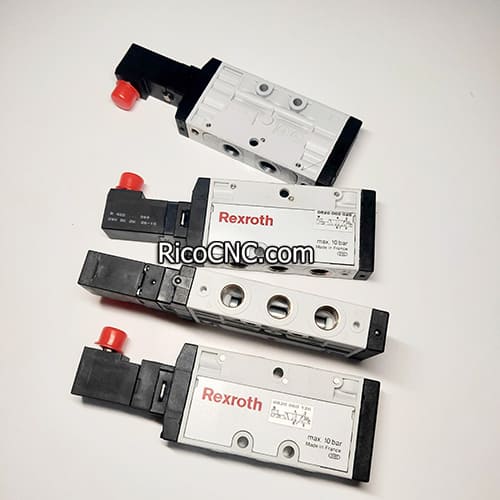
Frequently Asked Questions
1. How do I choose the right type of limit switch?
Selecting the right limit switch depends on your application requirements—considering factors like motion type, environmental conditions, and actuation force.
2. What are NO and NC terminals in a limit switch?
NO (Normally Open) and NC (Normally Closed) refer to the state of the switch when it is not activated. NO closes when actuated, whereas NC opens upon activation.
3. How can I tell if my limit switch is working?
You can verify the functionality using a multimeter to test continuity. There should be a change in resistance as the actuator moves between open and closed states.
4. Can limit switches be used in high-temperature environments?
Yes, but only if rated for high temperatures. Specialized high-temperature limit switches are available for such applications.
5. What is the primary function of a limit switch in automation?
The primary function is to detect an object's presence or movement and provide feedback to control machinery operations, ensuring safe and precise movement.
Conclusion
Connecting a limit switch involves understanding the type of switch, selecting the correct terminals, ensuring proper mounting, and testing the circuit to ensure it functions as intended. By following these guidelines, you can successfully connect a limit switch that operates efficiently and enhances the safety of your machinery.
If you are unsure about any part of the process or have more complex requirements, it is advisable to consult with a professional technician. Proper installation and maintenance of limit switches are critical for system reliability and safety. Don't hesitate to reach out if you need more detailed information or assistance with specific products related to limit switches and automation components.
